

Unit Coordinator & Lecturer
Dr. Naeha Sharif
Lab Facilitators
David Charkey
Jasper Paterson
Consultation Time
Thursdays, 3:00-4:00pm.Where: Room 1.05 in CSSE
and online (active in consultation hour)
News:
- [28 Feb'22] Welcome to CITS3003
4D Transformations, Callbacks and Meshes
Objectives:
In this lab's exercises, you will learn how to:- Extend 3D transformation matrices to 4D which allows translations, which are transformations that directly change the location of the origin, and hence also all vertices that are drawn relative to it.
- Use library functions from
mat.hfor standard transformations: rotation, scaling, translation and perspective transformation. - Set simple resize, mouse and timer callback functions.
- Share vertex data between triangles by drawing using
glDrawElementsand set up multiple vertex array objects so that many different objects can be drawn.
You should try to complete this lab during the lab session. If you lag behind, try to complete it in your own time.
Continuing from last time
- Create a new folder
lab5and then the folderlab5/LINUX_VERSIONS. Copy theMakefilefrom lab4 to there. - Copy, rename and modify the C++ code and vertex and fragment shaders from previous labs as you need them in what follows.
- Create a new folder
Q1: Translations via 4D matrices
In lab 4 you shouldn't have needed to change the vertex shader at all (nor the fragment shader). Being able to pass a 3D matrix to the shader allows us to do many different geometric transformations, including all possible rotations and scaling. However, it doesn't allow us to move objects to a different place - no matter what 3 by 3 matrixMwe choose, we have
M O = O
whereO = (0,0,0)Tis the origin. That is, matrix M times the origin gives the origin. There is no translation in all the code that we have written so far.
To allow objects to move, or be translated, we could modify our vertex shader to separately take in a
vec3 moveTowhich it adds to the coordinates of each vertex to move the origin to the designated position. But, this wouldn't allow us to combine these translations within a sequence of rotation and scaling transformations.
A better way is to add a fourth dimension to every vertex position that is always just the constant 1.0. Then, in our matrices the entries in the fourth column (dx, dy, dz, 1) are mutiplied by 1.0, so they are added to the coordinates of every vertex, causing a translation that moves the origin to the position (dx, dy, dz). The 1 at the bottom of the fourth column ensures that the result of any matrix multiplication also has a 1 in the fourth position.
This results in 4D Homogeneous Coordinates which are central to OpenGL and other similar graphics APIs.
-
- Take a copy of the vertex shader from the last lab, and generalise it so that it takes in
a 4D matrix and position instead of 3D, and simply multiplies them to produce the
output position:
gl_Position = xyzwMultipliers * vPosition;
- Similarly, take a copy of the C++ code for the second version in Q7 from last time,
and set it to use the new vertex shader (and a copy of the previous vertex shader), passing
a 4D matrix via
glUniformMatrix4fv. - Instead of putting matrices directly in the C++ code for the display function as in previous labs,
we'll use functions from the
mat.hlibrary that produce 4D matrices that we can multiply together.Replace the previous 3D matrices with the following 4D matrix multiplication:
RotateX(angleDegrees) * RotateY(angleDegrees) * Scale(0.25, 1.0, 1.0)
Here you'll need
angleDegreessimilar to the previousangle, just in degrees rather than radians (hint: 180 degrees = 3.1416 radians, approximately). - Make and run this program, and verify that it does the same as the last program in the previous lab, i.e, the same as the right-hand part of the video below.
- Take a copy of the vertex shader from the last lab, and generalise it so that it takes in
a 4D matrix and position instead of 3D, and simply multiplies them to produce the
output position:
-
- Now, replace the scaling with
Translate(0.6, 0.6, 0.6). What difference does this make? (Warning: part of the cube will go outside the viewing volume, causing an apparent "hole" in place of one corner - rememeber this because it's likely you'll encounter similar in future.) - Rather than
create different versions and then experiment to
see what happens when we move the translation to before or after each of the rotations,
we cam use scaling and translation to display four things in different parts of the window.
Compare (a) the original (without the translation) with three versions (b) with the translation to the right of both rotations, (c) between the rotations and (d) to the left of both rotations.
Do this comparison by dividing the screen into four parts (top-left, top-right, bottom-left, bottom-righ), and in each part one draw of these four. To do this you'll need to start the multiplication with, e.g,
Translate(0.5, 0.5, 0) * Scale(0.3) * ...to scale all dimensions down by
0.3and then move the origin to(0.5, 0.5, 0.0), the centre of one of the four parts.
In each of the four parts also draw the rotated cube with no translation, to help compare the effects of the translations.
Rather than repeat the code that draws the cube, use the following function that takes in a 4 by 4 matrix, sets it, and then draws a cube.
void drawCube(mat4 model) {
    glUniformMatrix4fv( xyzwMultipliers, 1, GL_TRUE, model );
    glDrawArrays( GL_TRIANGLES, 0, NumVertices );
}
Here the matrix transforms from object coordinates (relative to the objects own origin and axes) to world coordinates (the coordinates used to describe positions in the world). Such a matrix is called a model matrix.
- Make and run yor program and compare to the following video.
- Now, replace the scaling with
-
Q2: Perspective transformation
Themat.hlibrary/header also includes a function for creating 4D matrices that perform perspective transformations. This function has the form:mat4 Frustum( const GLfloat left, const GLfloat right, const GLfloat bottom, const GLfloat top, const GLfloat near, const GLfloat far )Here the camera is at the origin, and
left, right, bottom, topgive the coordinates of a rectanglenearunits in front of the camera, with rays from the camera projecting onto this rectangle following the synthetic camera model.fardetermines the largest distance in front of the camera included in the viewing volume.Together the parameters describe a pyramid with it's "point" at the origin (where the camera is), but with some of the pointy part removed - a shape properly called a frustum. Generally
nearandfarshould be positive, withnear < farandleft < right, andbottom < top.See the following figure [from the recommended text ]:
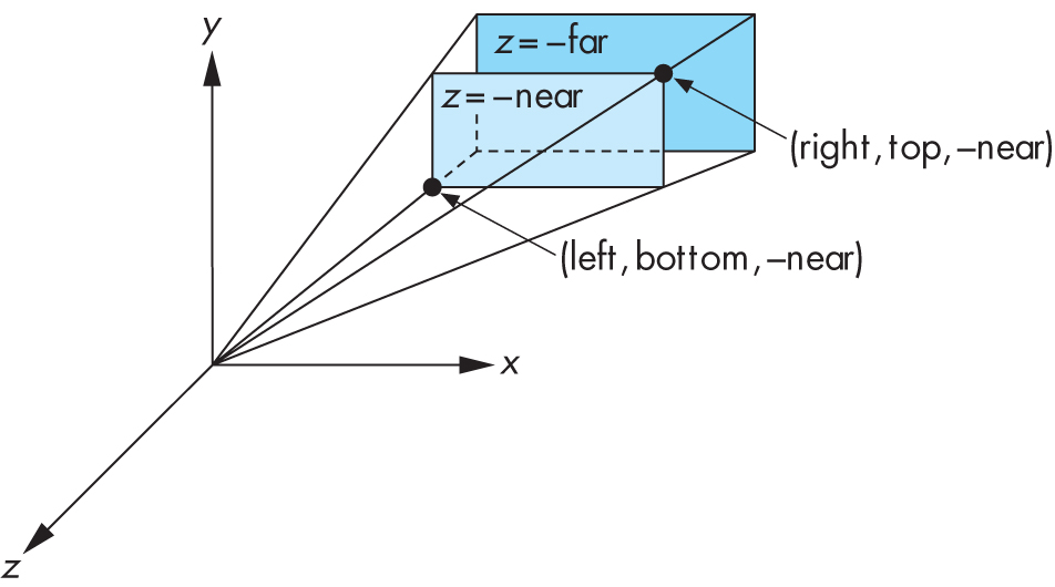
The camera is at the origin, and most commonly
left = -rightandbottom = -top.The
Frustumfunction is designed so that multiplying coordinates by the matrix it returns will map points within the specified frustum to corresponding points in the standard OpenGL viewing volume (i.e, -1 to 1 in the x, y and z directions). Thus, it's common to have use Frustum for the last matrix in a multiplication, i.e., the leftmost one. We say that this matrix converts from camera coordinates (position relative to the camera) to normalized device coordinates (with x and y locations corresponding 2D window locations in the range -1 to 1) which are closely related to window coordinates (with x and y locations in pixels). Such a conversion is called a projection transformation, and often it is kept in a special variable because it only changes when the basic properties of the camera change, such as the when the window is reshaped.Note that viewing using
Frustumgenerally requires that the objects are in front of the camera, and often this means a translation is required to move the camera backwards relative to the rest of the "world" (or move the world further along the negative z-axis). More generally, we say that there is a conversion from world coordinates (the ones we use when placing objects in our scene) to camera coordinates (realtive to the camera), and call this the view transformation generally represented by a view matrix.- Take a copy of the previous program and add as global variables near the top of the C++ code:
// Perspective projection
mat4 projection = Frustum(-0.2, 0.2, -0.2, 0.2, 0.2, 2.0);

// Move the scene backwards relative to the camera
mat4 view = Translate(0.0, 0.0, -1.5);
- Add the multiplications
projection * view *in front ofmodelwhen passing the transformation matrix to the vertex shader indrawCube. - Make and run the program, and compare with the video below.
- Take a copy of the previous program and add as global variables near the top of the C++ code:
Q3: Resize, mouse and timer callbacks
-
- Add global variables
GLint windowWidthandGLint windowHeight, and useglutReshapeFuncto register a callback function that updates these variables.
- This callback should also resize the viewport (the part of the window where
drawing occurs) via:
glViewport(0, 0, windowWidth, windowHeight); - Additionally, have the callback put a new projection matrix in
the
projectionglobal variable each time the window is resized. The new matrix should ensure that no "stretching" happens when the window isn't square - instead the ratio between the height and width should be used to modify theleftandrightparameters toFrustum.
- Add global variables
- Use
glutMotionFuncto add a callback when the mouse is moved with a button down. The callback should use the x and y coordinates of the mouse to set the x and y coordinates of the camera, by setting theviewglobal variable to a new matrix.
- Use
glutTimerFuncto add a callback that runs one second later, at which point it updates the window title with the number of times the display function was called within that one second period. You can just use the following code for the timer function:void timer(int unused) { char title[256]; sprintf(title, "%s %s: %d Frames Per Second @ %d x %d", lab, programName, numDisplayCalls, windowWidth, windowHeight ); glutSetWindowTitle(title); numDisplayCalls = 0; glutTimerFunc(1000, timer, 1); }You'll need to copy the call to
glutTimerFuncto the main function also, to start the timer the first time. Plus, you'll need to add the following global variables near the top of your C++ program:int numDisplayCalls = 0; char lab[] = "Lab5"; char programName[] = "q3callbacks";
Lastly, you'll need to increment
numDisplayCallsin your display function.
-
Q4: Sharing vertex data via glDrawElements
WhileglDrawArraysis the simplest way to draw in OpenGL, it isn't the most efficient because it generally requires the coordinates of a vertex to be repeated each time it appears in a triangle, which can be up to 6 times even with our simple cube.
To avoid this inefficiency, most complex 3D objects are stored as an array of vertices followed by an array of triangles with each triangle consisting of three integers that each specify the vertex by giving an integer index to refer to an element in the array of vertices.OpenGL supports drawing objects in this format via the function
glDrawElements.Create a copy of the code for the previous question and modify as follows so that it uses
glDrawElementsinstead ofglDrawArrays.- Put the following code in place of the previous definitions
of
points,colors, etc.:const int NumTriangles = 12; const int NumVertices = 8; const int NumElements = 3 * NumTriangles; // Each vertex now appears only once, so we have only 8 rather than 36 vec3 points[NumVertices] = { vec3( -0.5, -0.5, -0.5 ), vec3( -0.5, -0.5, 0.5 ), vec3( -0.5, 0.5, -0.5 ), vec3( -0.5, 0.5, 0.5 ), vec3( 0.5, -0.5, -0.5 ), vec3( 0.5, -0.5, 0.5 ), vec3( 0.5, 0.5, -0.5 ), vec3( 0.5, 0.5, 0.5 ) }; // The following builds triangles from the 8 vertices above, // using numbers 0-7 to refer to the element positions in the array GLuint elements[NumElements] = { 1, 5, 3, 7, 3, 5, 0, 4, 2, 6, 2, 4, 4, 6, 5, 7, 5, 6, 0, 2, 1, 3, 1, 2, 2, 3, 6, 7, 6, 3, 0, 1, 4, 5, 4, 1 }; // We only need to give 8 colors, one for each vertex. vec3 colors[NumVertices] = { vec3(0.0, 0.0, 0.0), vec3(0.0, 0.0, 1.0), vec3(0.0, 1.0, 0.0), vec3(0.0, 1.0, 1.0), vec3(1.0, 0.0, 0.0), vec3(1.0, 0.0, 1.0), vec3(1.0, 1.0, 0.0), vec3(1.0, 1.0, 1.0), };Add the following after the calls to
glBufferSubData:// ADDED: load the element index data GLuint elementBufferId; glGenBuffers(1, &elementBufferId); glBindBuffer(GL_ELEMENT_ARRAY_BUFFER, elementBufferId); glBufferData(GL_ELEMENT_ARRAY_BUFFER, sizeof(elements), elements, GL_STATIC_DRAW);Replace the call to
glDrawArrayswith:glDrawElements(GL_TRIANGLES, NumElements, GL_UNSIGNED_INT, NULL);Make and run your program - it should do the same thing, aside from the colours being different.
It may seem that these changes haven't achived much, but for the project we'll be loading large arrays of vertex and triangle data for models, which will require using elements/indices in order to draw the models directly.
- Put the following code in place of the previous definitions
of
Sample Solutions
All files at once:
lab5-soln.zip
Unzip this so that you have the lab5-soln
under your labs-examples folder, then build using make as usual.
Department of Computer Science and Software Engineering
University information
CRICOS Code: 00126G
This Page
Website Feedback:
naeha(dot)sharif(at)uwa(dot)edu(dot)au