

Unit Coordinator & Lecturer
Dr. Naeha Sharif
Lab Facilitators
David Charkey
Jasper Paterson
Consultation Time
Thursdays, 3:00-4:00pm.Where: Room 1.05 in CSSE
and online (active in consultation hour)
News:
- [28 Feb'22] Welcome to CITS3003
Drawing in 3D
Objectives:
In this lab's exercises, you will learn how to:- Display only fragments that are in front of others according to a depth test.
- Combine a sequence of 3D rotations by multiplying their matrices together.
- Compare the effect of multiplying 3D matrices in different orders.
- Extend this to sequences that include 3D matrices for scaling.
You should try to complete this lab during the lab session. If you are behind, then
try to catch up the lab exercises in your own time.
Continuing from last time
- Check the sample solutions for lab 3.
- Create a new folder
lab4/LINUX_VERSIONSorlab4/MAC_VERSIONSand copy theMakefilefrom lab3. E.g., via:
cd ~/cits3003/labs-examples
mkdir lab4; cd lab4;
Then, depending on what platform you use, type:
mkdir LINUX_VERSIONS; cd LINUX_VERSIONS
cp ../../lab3/LINUX_VERSIONS/Makefile .
or
mkdir MAC_VERSIONS; cd MAC_VERSIONS
cp ../../lab3/MAC_VERSIONS/Makefile .
- Copy, rename and modify the C++ code and vertex and fragment shaders from previous labs as you need them in what follows.
Q1: 3D rotating square
- Combine the 3D rotation code from the end of the last lab with the code from lab 2
that drew a coloured square. Make the square rotate in the x and z dimensions.
Hint: you may find it easier to start with the C++ code from lab 2, then alter it to use the vertex shader from the end of lab 3. - Change the colours so that when a vertex appears in both triangles, it has the same
colour in both - so that the shading is smooth across the square (this will help
make it clear which square is which in what follows).
- Make and run your program.
Sample for rotating a coloured square in the x and z directions.
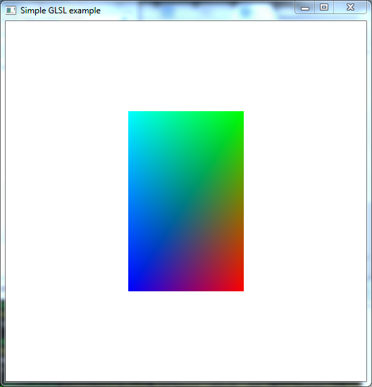
- Combine the 3D rotation code from the end of the last lab with the code from lab 2
that drew a coloured square. Make the square rotate in the x and z dimensions.
Q2: multiple 3D squares rotating in different dimensions
- Now, add a second square rotating in the x and y dimensions by modifying the
display function to add a second
call to
glUniformMatrix3fvwith the appropriate matrix, followed by a second call toglDrawArrays. - Similarly add a third square rotating in the y and z dimensions by adding calls to the display function after the code for the other two squares.
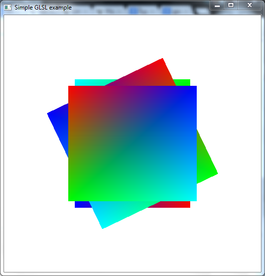
- Make and run your program. You should see something like the following samples -
with the square in front being the one drawn last. This is because each call to
glDrawArrayssimply overwrites the appropriate parts of the framebuffer.
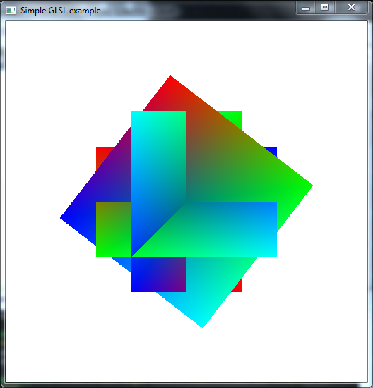
Samples for rotating three coloured squares without hidden surface removal.
- Now, add a second square rotating in the x and y dimensions by modifying the
display function to add a second
call to
Q3: 3D rotating squares with hidden surface removal.
- The object that appears in front in the previous question doesn't properly reflect the z-coordinates, instead it just reflects the order that the objects were drawn. For realistic 3D graphics instead we want to only see the parts of each square that are in front of the other squares. We could try to do this by breaking each square up and only drawing the visible parts of each, which would change as they rotate, but this is difficult, and doesn't scale well when many complex objects are involved. OpenGL provides an easier way: depth testing which involves storing the distance from the viewer each time a fragment affects a pixel in the framebuffer, skipping fragments that are further than a previously drawn fragment for that pixel. We almost always want to use this when drawing in 3D in OpenGL.
- To enable depth testing, three things are required:
- We need to request bits to store the depth of each pixel by adding
GLUT_DEPTHto the display mode requested in the call toglutInitDisplayMode, e.g.:glutInitDisplayMode( GLUT_RGBA | GLUT_DOUBLE | GLUT_DEPTH );
- We need to enable depth testing during drawing by adding the following to the
initfunction (or anywhere after the window is created):glEnable( GL_DEPTH_TEST );
- We need to clear the depths before we start each redrawing of the window. Generally this means adding
GL_DEPTH_BUFFER_BITto the call toglClearat the start of the display function:glClear( GL_COLOR_BUFFER_BIT | GL_DEPTH_BUFFER_BIT );
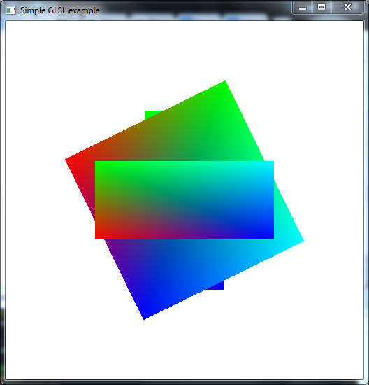
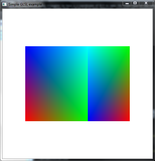
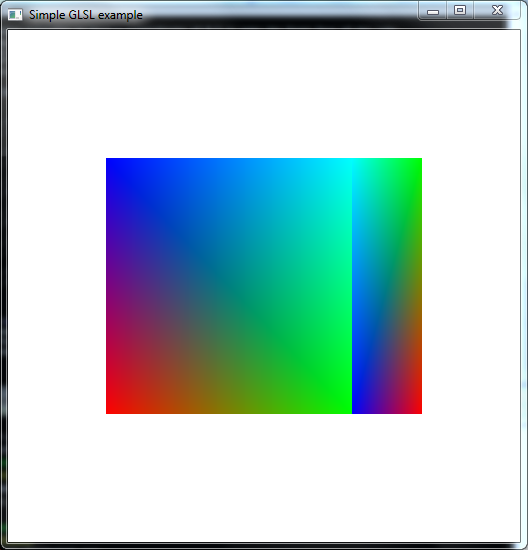
Samples for rotating three coloured squares with hidden surface removal.
- We need to request bits to store the depth of each pixel by adding
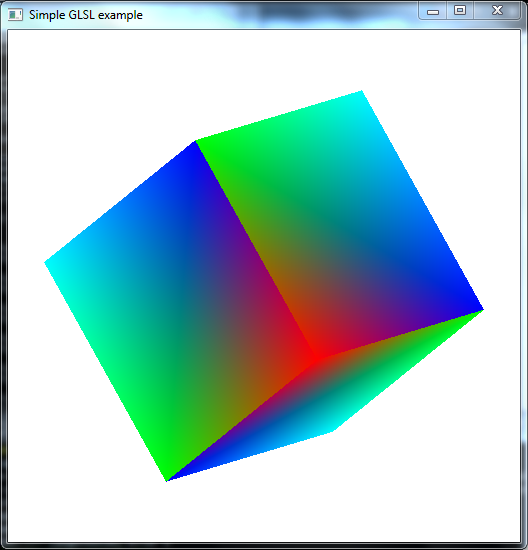
Q4: 3D rotating cube
- Now, recall from the start of lab 2 that we originally drew a square as a front face of cube - a face that's directly facing the viewer. We didn't draw the other faces because in this case they are all behind the front face. In doing so, we manually performed hidden surface removal. But, once we start rotating a cube, the other faces become visible depending on the angle, and we can use depth testing to automatically remove the hidden parts of the faces.
- Take a copy of the previous C++ code.
- EITHER:
- Move the two existing triangles to have a z-coordinate of 0.5 to make the front face of the cube. (Note that the viewing volume ranges from -1.0 to 1.0 in each dimension, including the z dimension.)
- Make a second copy of the triangles for the back face with z-cooordinate of -0.5.
- Make two copies of the front and back faces, and swap the x, y and z coordinates of
these two faces to make the other 4 faces
vec3 points[NumVertices] = { vec3( -0.5, -0.5, 0.5 ), vec3( 0.5, -0.5, 0.5 ), vec3( -0.5, 0.5, 0.5 ), vec3( 0.5, 0.5, 0.5 ), vec3( -0.5, 0.5, 0.5 ), vec3( 0.5, -0.5, 0.5 ), vec3( -0.5, -0.5, -0.5 ), vec3( 0.5, -0.5, -0.5 ), vec3( -0.5, 0.5, -0.5 ), vec3( 0.5, 0.5, -0.5 ), vec3( -0.5, 0.5, -0.5 ), vec3( 0.5, -0.5, -0.5 ), vec3( 0.5, -0.5, -0.5 ), vec3( 0.5, 0.5, -0.5 ), vec3( 0.5, -0.5, 0.5 ), vec3( 0.5, 0.5, 0.5 ), vec3( 0.5, -0.5, 0.5 ), vec3( 0.5, 0.5, -0.5 ), vec3( -0.5, -0.5, -0.5 ), vec3( -0.5, 0.5, -0.5 ), vec3( -0.5, -0.5, 0.5 ), vec3( -0.5, 0.5, 0.5 ), vec3( -0.5, -0.5, 0.5 ), vec3( -0.5, 0.5, -0.5 ), vec3( -0.5, 0.5, -0.5 ), vec3( -0.5, 0.5, 0.5 ), vec3( 0.5, 0.5, -0.5 ), vec3( 0.5, 0.5, 0.5 ), vec3( 0.5, 0.5, -0.5 ), vec3( -0.5, 0.5, 0.5 ), vec3( -0.5, -0.5, -0.5 ), vec3( -0.5, -0.5, 0.5 ), vec3( 0.5, -0.5, -0.5 ), vec3( 0.5, -0.5, 0.5 ), vec3( 0.5, -0.5, -0.5 ), vec3( -0.5, -0.5, 0.5 ), }; - Increase
NumTrianglesto 12. - Copy the colors so there's enough for all 12 triangles, i.e, 36 vertices.
- Draw the cube rotating in the x and z dimensions only. So comment out the code in the display function for the other two ways of rotating that we used for the square.
- Make and run your program.
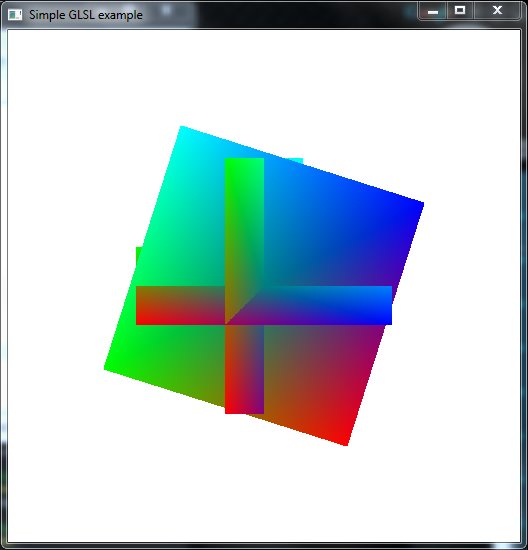
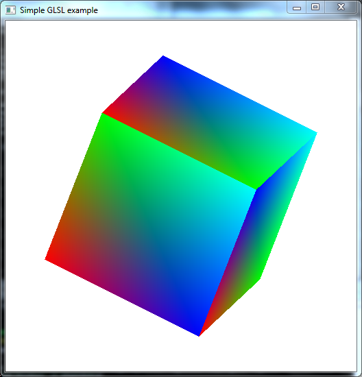
Samples for rotating a coloured cube and the x and z directions with hidden surface removal.
Q5: General 3D rotations via matrix multiplication
Now, suppose we want to rotate our cube in other ways. We know how to create matrices that rotate in the y-z dimensions, x-z dimensions and the x-y dimensions (or equivalently, around the x-axis, the y-axis and the z-axis). But, this is still very limiting - there are many other ways a cube can be rotated.
One way to allow more general rotations is to combine the three rotations we know together: first rotate around the x-axis, then rotate the result around the y-axis and finally rotate around the z-axis. (This in fact allows us to form any rotation.)We could create the three rotation matrices in our C++ program and pass all three to the vertex shader so that it can multiply each vertex by the three matrices, one after the other with code like:
gl_Position.xyz = zRot * (yRot * (xRot * vPosition));
But, by the magic of linear algebra/matrices this is equivalent to:
gl_Position.xyz = (zRot * yRot * xRot) * vPosition;
So, we can just multiply the three matrices together and then pass them to the same vertex shader as previously.
- Take a copy of your C++ code for the previous question.
- Uncomment (or copy from Q3) the code that calculates the other two rotations.
- Multiply these rotations together and pass the result to the vertex shader
prior to calling
glDrawArrays. - Make and run your program.
Samples for general 3D rotations via composition.
Q6: Rotating via matrix multiplication: the order matters!
Note that the order we multiply the rotations matrices matters in the previous question. We first rotate the coordinates of the vertices around the x-axis, and then rotate them around the y-axis - but this isn't the same as the y-axis for the original cube (unless the x-axis rotation is zero, or a multiple of 2π). (Then, similarly we rotate around the resulting z-axis.)- Make two copies of your C++ code for the previous question.
- Set the first copy to rotate first around the x-axis and then around the y-axis -
i.e., multiply the matrices around the y-axis and x-axis as:
rotY * rotXSince the whole calculation for a vertex will be
rotY * rotX * vPositiontherotYhappens second, causing the front face to consistently rotate towards the left, with therotXadding some rotation towards the top or bottom depending on the current y-axis rotation. - Set the second copy to rotate first around the y-axis and then around the x-axis,
i.e.:
rotX * rotY
Since therotXhappens second, the front face consistently rotates towards the bottom, with therotYadding some rotation towards the left or right depending on the current x-axis rotation. - Make both programs and run them side-by-side by running the following command to run both at once, and then move
one of the windows using the mouse so that they are next to each other:
./q6rotYrotXcube & ./q6rotXrotYcube &
See the following video. The first version should generally have the front face moving towards the right, but also varying between moving upwards and downwards, while the second one should generally have the front face moving towards the top, but also varying between moving leftwards and rightwards.
- Make two copies of your C++ code for the previous question.
Q7: The order matters when adding 3D scaling too
We can also scale some or all of the coordinates by pre-multiplying them by appropriate matrices. E.g., the following matrix shrinks the x-coordinates by a factor of 4:mat3 shrinkX = mat3( vec3(0.25, 0.0, 0.0), vec3(0.0, 1.0, 0.0), vec3(0.0, 0.0, 1.0) );- Make two copies of your C++ code for the second version (with rotX * rotY) in the previous question.
- In the first copy, add a multiplication by
shrinkXto the left of the two rotations. - In the second copy, add a multiplication by
shrinkXto the right of the two rotations. - Make both programs and run them side by side to see the difference.
See the following video. The first version should directly reduce the final x-coordinates so everything ends up looking "squeezed" in the centre. The second version should instead reduce the original x-coordinates so that instead of a cube we get a box with one dimension a quarter of the other two.
As in the previous question, the point here is that the order that we put the matrices matters when we multiply them. The general rule is that each matrix is given the coordinates after they've been transformed by the matrices to the right of it.
Sample Solutions
All files at once:
lab4-soln.zip
Unzip this so that you have thelab4-solnunder yourlabs-examplesfolder, then build using make as usual.
Department of Computer Science and Software Engineering
University information
CRICOS Code: 00126G
This Page
Website Feedback:
naeha(dot)sharif(at)uwa(dot)edu(dot)au