Simplified Satellite Broadcasting
As an introduction to Local Area Networking,
and multiaccess communication,
let's take a very simplified look at satellite broadcasting:
- Many users share a single channel.
- Propagation at the speed of light, 300 000 km/sec.
- However, the distance travelled is large -
35,880km for conventional TV satellites,
resulting in round trip times of ~270-700msec.
We can contrast this with the emerging constellations
of Low Earth Orbit (LEO) satellites between 200-2000km,
with round trip times of ~35msec.
- Bandwidth,
typically 500Mbps,
is currently 5x higher than typical LAN-based networks
because it is less limited by the speed of local infrastructure.
- Cost is the same whatever the distance between sender and
receiver. Satellite costs have dropped dramatically in the last few years.
- Satellite acts as a repeater of incoming signals,
amplifying and re-broadcasting these signals.
- If two stations broadcast simultaneously the satellite will receive
and re-broadcast the sum of these two signals, resulting in garbage.
Such simultaneous broadcasts are termed collisions.
- A sender can listen to the re-broadcast of their own packets and
determine whether a collision has occurred.
Notice that there are no acknowledgements.
- Users are uncoordinated and can only communicate via the channel.
CITS3002 Computer Networks, Lecture 4, Local Area Networks (LANs and WLANs), p1, 20th March 2024.
Implications for Network Protocols
Therefore, the satellite channel must control its own allocation:
The advantages of this "shared medium" approach are:
- No Data Link Layer acknowledgements needed,
each sender can verify the correctness of their own messages
(because they can hear them).
- No routing problems in the Network Layer subnet (no subnet!).
- No congestion problems or topology optimization.
- Mobile users may be supported.
The disadvantages of this approach are:
- Long propagation delay of at least 270msec.
- All users receive all messages,
introducing security implications,
and there can be no central control of unethical users.
Question:
How can a single communication channel be efficiently shared between
uncoordinated users?
CITS3002 Computer Networks, Lecture 4, Local Area Networks (LANs and WLANs), p2, 20th March 2024.
Conventional Channel Allocation
We can employ two common schemes to share the medium:
- Polling
-
Either the satellite or a ground station offers
the channel to an individual user for a specified amount of time.
Delays of 270msec make this impractical.
Who should be polled?
Should priorities be given to the 100s or 1000s of potential customers?
- Frequency and Time Division Multiplexing
-
There are two significant forms -
frequency division multiplexing allocation (FDMA) and
time division multiplexing allocation (TDMA).
Using FDMA the channel is divided into N frequency bands (slots) for a
maximum of N users.
Guard bands are placed between these to limit interference.
Using TDMA the channel is divided into slots based on time intervals,
typically 125usec.
Each potential user may then use the whole channel for their time quantum
(in a manner similar to operating system timesharing).
Both FDMA and TDMA are very inefficient since the actual number of users, M,
is generally <<N or >>N, and traffic is often 'bursty'.
CITS3002 Computer Networks, Lecture 4, Local Area Networks (LANs and WLANs), p3, 20th March 2024.
Pure ALOHA
In 1970 Norman Abramson devised the ALOHA network at the University of
Hawaii.
Pure ALOHA uses a contention based protocol:
- Users transmit whenever they wish.
- Users detect their own collisions.
- After a collision, a user 'backs-off' for a random time period and
then retransmits.
What are our expectations for throughput of this approach?
- Infinite number of users each thinking and sending.
- Generation of packets is a Poisson distribution,
with mean S.
Here, S = number of packets generated per packet time.
If S > 1 we have chaos.
If 0 < S < 1 we get acceptable throughput.
Analysis can show the best possible utilization of 18.38%.
CITS3002 Computer Networks, Lecture 4, Local Area Networks (LANs and WLANs), p4, 20th March 2024.
Slotted ALOHA (1972)
The slotted Aloha mechanism makes an obvious improvement to
improve expected throughput:
- the satellite generates a timing pulse.
- users then only transmit when they get this pulse.
This quantization of time reduces the vulnerability period by half
(now to a single packet transmission time).
Hence :
S = G * e -G
Maximum throughput is now achieved when G = 1,
giving S = 1 / e
or a best possible utilization of 36.79%.
Note that small increases in G dramatically reduce performance.
CITS3002 Computer Networks, Lecture 4, Local Area Networks (LANs and WLANs), p5, 20th March 2024.
Local Area Networks
Let's use an informal definition to characterize our next topic of study,
local area networks:
| Activity |
Separation |
Bit rate |
| Wide area networks, WANs |
> 10km |
< 100.0 Mbps |
| Local area networks, LANs |
10 → 0.1km |
100.0 → 10,000Mbps |
| Multiprocessors |
<< 0.1km |
> 1Gbps |
In particular, for local area networks:
- Machines connect to a (logically) single cable within a 1km radius
(often the same building or campus).
- Total data rate > 10Mbps
(short round trip time, simple data link layer with, say, a one bit sliding
window)
- Single organization ownership (no political domains to traverse).
- Usually use broadcasting
(no routing problems, but everyone sees all frames).
One general definition, often cited, is:
|
"A LAN is a routerless network, using the
same protocol stack for each device,
and using only a uniform, local, networking media."
|
CITS3002 Computer Networks, Lecture 4, Local Area Networks (LANs and WLANs), p6, 20th March 2024.
Carrier Sense Networks
- All stations can sense the electrical carrier before sending.
- This is possible because of the use of high speed cables over short
distances.
We will be concerned with carrier-sense multiple-access (CSMA)
protocols.
Factors Affecting CSMA LANs
- All frames are of constant (or small, bounded) length.
- There are no transmission errors, other than those of collisions.
- There is no capture effect.
- The random delay after a collision is uniformly distributed and
large compared to the frames' transmission time.
- Frame generation attempts (OLD and NEW) form a Poisson process with
mean G frames per time.
- A station may not transmit and receive simultaneously.
- Each station can sense the transmission of other stations.
- Sensing of the channel state can be performed at the same time as
transmitting.
- The propagation delay is small compared to the frames' transmission
time, and identical for all stations.
CITS3002 Computer Networks, Lecture 4, Local Area Networks (LANs and WLANs), p7, 20th March 2024.
Persistent CSMA Protocols
Using
1-persistent CSMA protocols,
each station first senses the activity on the channel.
If two stations A and B are waiting for C to finish,
they just pause for a period,
and when they sense that the channel is free,
transmit with a probability of 1 (pretty persistent eh?).
This, naturally, results in a good chance of a collision.
The longer a propagation delay on a LAN the more collisions there will be
and, hence, the worse will be the performance.
1-persistence is no good for satellite broadcasting because :
each station hears what was happening at least 270msec ago!
CITS3002 Computer Networks, Lecture 4, Local Area Networks (LANs and WLANs), p8, 20th March 2024.
Non- and p-persistent CSMA Protocols
In non-persistent and p-persistent protocols,
each station may again sense a busy channel.
If the channel is found too busy,
contending stations 'back-off' for various intervals.
- Non-persistent stations back-off for random intervals.
- p-persistent stations 'jump in' with a probability p
(or back-off for a constant amount of time
with a probability q=1-p
Obviously, the lower the value of p the fewer collisions there will
be (each station is almost 'chicken' to transmit).
Even though the channel utilization can approach its maximum,
each station can be waiting a long time.
CITS3002 Computer Networks, Lecture 4, Local Area Networks (LANs and WLANs), p9, 20th March 2024.
IEEE-802.x LAN Standards - The Ethernet System
Devised by Metcalfe and Boggs (1976) from Xerox Parc,
(CACM, July 1976, pp395-404).
The 'Ethernet' system is a member of the IEEE-802 family of protocols
for local area networks (it is 802.3).
802.3 uses a 1-persistent Carrier-Sense Multiple-Access with Collision
Detection (CSMA/CD) method.
See:
CITS3002 Computer Networks, Lecture 4, Local Area Networks (LANs and WLANs), p10, 20th March 2024.
Physical Properties
The original 'standard' Ethernet proposal was for a 3Mbps network,
connecting up to 256 stations (1975).
The IEEE-802.3 standard has since been introduced which at first supported up to
1024 stations at 10Mbps over a total length not exceeding 2.5km.
| Type |
Cable |
Max. Segment |
Nodes/seg. |
Advantages |
| 10Base5 |
Thick coax |
500m |
100 |
Used for backbones |
| 10Base2 |
Thin coax |
185m |
30 |
Cheaper |
| 10Base-T |
Twisted pair |
100m |
1024 |
Easy maintenance |
| 10Base-FX |
Fiber optic |
2000m |
1024 |
Best between buildings |
- Each packet must be at least 64 bytes long to provide some reasonable
chance of detecting collisions over long-ish propagation times.
- Due to power losses within the Ethernet cables,
each segment cannot exceed 500m, so repeaters were used to connect
up to 5 segments in a single LAN.
- Later additions to the 802.3 standard support increasingly faster
twisted pair speeds: 100Base-T, 1000Base-T, and recently 10GBase-T.
- Similarly, fiber optic speeds and segment lengths have increased: 10GBase-ER
(extended range) allows 40km. 100Gbps is in the works.
More recently, there has been an 'explosion' in wired Ethernet categories:
- Standard: 10Base5, 10Base2, 10BaseT, 10BaseFX
- Fast: 100BaseTX, 100BaseT4, 100BaseFX
- Gigabit: 1000BaseT, 1000BaseLX
- 10-Gigabit: 10000BaseT, 10000BaseLR
CITS3002 Computer Networks, Lecture 4, Local Area Networks (LANs and WLANs), p11, 20th March 2024.
Ethernet's Contention Algorithm
Each station wanting to transmit, listens to the ether and on finding it
silent begins transmission.
On detecting a collision a station:
- 'backs-off' for a random period which
is a multiple of the 802.3 slot time. (This time is chosen based on the
longest allowable path being 2.5km, and is set at 51.2microseconds).
- After the first collision each station backs-off
for 0 or 1 slot times before trying again.
If there is a second collision, a station backs-off
for 0, 1, 2 or 3 slot times.
- In general,
a station will back-off from 0 to 2i-1
slot times after the ith collision.
This continues for a maximum of 10 collisions
(1023 back-offs),
after which the station stays at 1023 for 6 more
collisions.
- After 16 collisions the station considers the 'ether' severed
and reports back to the Networking Layer.
This method, termed binary exponential back-off,
ensures a short delay for each station when a small number of stations
collide and a reasonable delay when many stations collide.
CITS3002 Computer Networks, Lecture 4, Local Area Networks (LANs and WLANs), p12, 20th March 2024.
Ethernet Addressing Schemes
Each 802.3 packet contains the source and destination address,
each of 6 bytes (48 bits).
- If all 48 destination bits are set to 1,
the packet is a broadcast address destined for all stations
on a LAN.
- The high-order bit (bit 47)
is used to indicate addressing domains,
0 being for individual addresses and 1 being for multicast
addresses (to deliver packets to a group of stations).
- Bit 46 (high-order less one) indicates whether the address is for the
current LAN or for a more global station on another LAN.
- Using 246 bits
(7 * 1013 stations) each device in the world
can have a unique Ethernet card number (assigned by the IEEE).
Of course it is up to the Network Layer to determine how to get to
other stations not on your LAN.
CITS3002 Computer Networks, Lecture 4, Local Area Networks (LANs and WLANs), p13, 20th March 2024.
Packet Transport Mechanisms
Each station connects to the ether with a transceiver.
'The design of the transceiver must be an exercise in paranoia'.
In particular, failures of the transceiver must not pollute the ether,
power failure must not 'cloud' the ether
and disconnection must not be noticed by other stations.
802.3 uses five significant mechanisms to reduce the probability and
cost of losing a packet.
CITS3002 Computer Networks, Lecture 4, Local Area Networks (LANs and WLANs), p14, 20th March 2024.
Packet Transport Mechanisms, continued
- interference detection.
Each transceiver has an interference detector;
a station can detect interference because what it is receiving is not what
it is transmitting.
Interference detection has three advantages:
- A station can detect collisions and re-schedule transmission (no need to
wait for a lack of acknowledgement).
- Interference is detected within the propagation time (with Aloha a whole
packet was transmitted and then examined for a collision).
- The frequency of collisions is immediately used to dynamically change the
back-off times.
- truncated packet filtering.
Interference detection and deference cause most collisions to result in
truncated packets of only a few bits.
To reduce the overhead of obviously damaged packets, the hardware
is able to filter them out.
- collision consensus enforcement.
Whenever a station detects a collision of its own transmission
it deliberately jams the ether to ensure that other colliding
stations hear the collision as quickly as possible and then to stop
transmitting.
CITS3002 Computer Networks, Lecture 4, Local Area Networks (LANs and WLANs), p15, 20th March 2024.
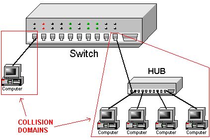
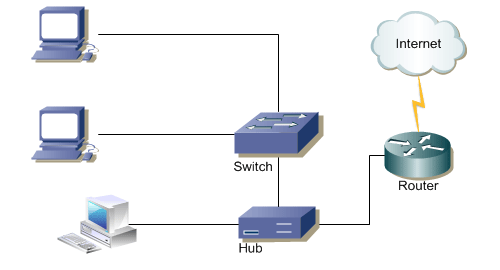
Hubs, Switches, and Collision Domains
A collision now occurs when a device or LAN-segment
receives two or more signals simultaneously.
Obviously our goal is to reduce collisions by either resolving them quickly,
or reducing the likelihood of them occuring at all.
The following diagram highlights the difference between a hub and a
switch, when node F is transmitting to node C.
The hub will retransmit the frame to all of its outgoing ports,
whereas the switch will more 'intelligently' retransmit the signal to the
ports known to be wanting the frame:
A collision domain is the set of devices (potentially) receiving a
frame collision.
Today, it is very difficult to purchase a hub,
as switches have become so inexpensive,
but hubs can still play a role in Ethernet traffic monitoring.
CITS3002 Computer Networks, Lecture 4, Local Area Networks (LANs and WLANs), p16, 20th March 2024.
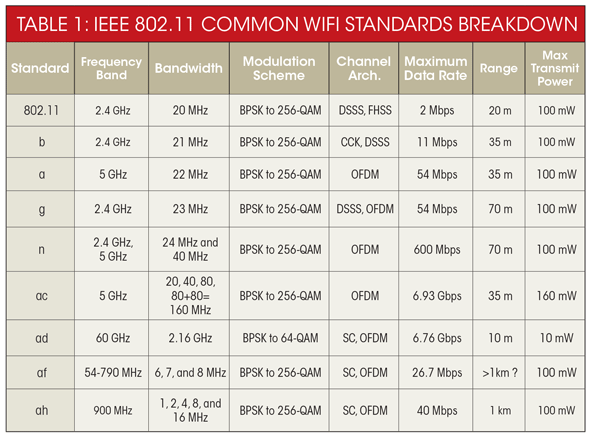
The IEEE-802.11 Wireless LAN protocol
We'll next examine devices implementing the IEEE-802.11
family of wireless networking protocols,
and get an appreciation of some of the security challenges.
|
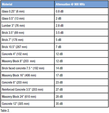
Often of interest is not simply the maximum possible transmission rate,
but the distance over which WiFi may operate.
We need an understanding of the transmission power, propagation,
and signal loss over distance and through objects.
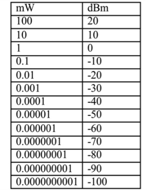
The unit dBm is defined as power ratio in decibel (dB) referenced to
one milliwatt (mW). It is an abbreviation for dB with respect to 1 mW and
the "m" in dBm stands for milliwatt.
dBm is different from dB. dBm represents absolute power, whereas dB is a
ratio of two values and is used to represent gain or attenuation. For
example, 3 dBm means 2 mW, and 3 dB means a gain of 2. Similarly, -3 dBm
means 0.5 mW, whereas -3 dB means attenuation of 2.
A WiFi access point (AP) will typically transmit at up to 100mW,
and a receiving device will typically be able to discern arriving signal
from noise until -90dBm.
|
|
|
CITS3002 Computer Networks, Lecture 4, Local Area Networks (LANs and WLANs), p17, 20th March 2024.
Hidden Node, Crouching Dragon Exposed Node
As a first guess, it would appear that the standard (wired) Ethernet
protocol should also work for wireless networks -
simply wait until the medium (airwaves) becomes clear, transmit, and then
retransmit if a collision occurs.
However, this simple approach will not work, primarily because not all
nodes are within range of each other.
Consider these two typical situations:
- (a) A wishes to send a frame to B,
but A cannot 'hear' that B is busy receiving a message from C.
If A transmits after detecting an idle medium,
a collision may result near B.
This is described as the hidden terminal or the hidden
node
problem. C is hidden from A, but their communications can interfere.
- (b) B wishes to transmit to C, but hears that A is transmitting (possibly
to someone to the left of A).
B incorrectly concludes that it cannot transmit to C, for fear of causing
a collision.
This is described as the exposed terminal or the exposed node
problem.
CITS3002 Computer Networks, Lecture 4, Local Area Networks (LANs and WLANs), p18, 20th March 2024.
802.11 Collision Avoidance
A further problem is that most wireless cards are unable to both transmit
and receive at the same time, on the same frequency -
they employ half-duplex transmissions.
This means that while collisions do occur, they generally cannot be
detected (while transmitting).
Unlike their 802.3 wired counterparts,
802.11 wireless LANs do not employ the
Carrier Sense Multiple Access with Collision Detection protocol
(CSMA/CD).
(pedantically, it is incorrect to call 802.11 as being 'wireless
Ethernet', but everyone does).
Instead, 802.11 employs collision avoidance to reduce (but not
eliminate) the likelihood of collisions occurring.
The algorithm is termed Multiple Access with Collision Avoidance (MACA),
or CSMA/CA,
in which both physical channel sensing
and virtual channel sensing are employed.
The basic idea is that before transmitting data frames,
the sender and receiver must first exchange additional control frames
before the 'true' data frames.
The succcess or failure of this initial exchange either
reserves the medium for communication between A and B,
or directs how A, B, and all other listening nodes should act.
CITS3002 Computer Networks, Lecture 4, Local Area Networks (LANs and WLANs), p19, 20th March 2024.
802.11 Collision Avoidance, continued
Consider the situation of 4 nodes.
You can imagine that we have 4 nodes left-to-right, named C, A, B, D.
- A wishes to communicate with B,
- C can hear only A, and
- D can hear only B.
- A observes an idle medium,
and initially sends a Request to Send (RTS) frame to B.
This frame includes a field indicating how long (in microseconds)
the actual data frame will be,
i.e. how long the sender wishes to hold the medium.
- When B receives the RTS it replies with a Clear to Send (CTS)
frame, also carrying the length of the data frame.
- Any other node hearing the RTS frame (e.g. C) knows that A is making a
request, and should not itself transmit until the indicated length/time
has elapsed.
- Any node hearing the CTS frame (e.g. D) must be close to the receiver
(B) and therefore should also not transmit for the indicated length of time.
- Any node that hears the RTS frame, but not the CTS frame,
knows that it is not close enough to the receiver to interfere,
and so is free to transmit (but must first transmit its own RTS...).
CITS3002 Computer Networks, Lecture 4, Local Area Networks (LANs and WLANs), p20, 20th March 2024.
802.11 Collision Avoidance, continued
There are two final considerations -
- When the receiver (B) successfully receives a data frame,
it must reply with an ACK frame.
All other nodes must wait for this ACK frame before they can transmit
their own RTS frames.
The additional ACK frames were not defined in the early MACA protocols,
but added to the Wireless MACA -> MACAW protocol used today.
- What if two nodes simultaneously issue an RTS?
If they are not in range, there is little problem,
we can have two transmission sequences in the same medium.
If the two RTS frames collide,
then any receivers will not be able to guess what they were,
and no CTS frame will be issued.
When no CTS arrives at the senders,
they assume a collision and undergo
the standard 802.3 binary exponential backoff algorithm.
CITS3002 Computer Networks, Lecture 4, Local Area Networks (LANs and WLANs), p21, 20th March 2024.
Access-Point Association
Although two mobile nodes can communicate directly,
the more usual approach is for all communication to be through fixed
access-points.
We say that a mobile node associates with a single access-point
if all of its communications are via that point,
and all such related nodes form a cell.
Communication between nodes in different cells requires two access-points
connected via a distribution system.
The mechanism employed by a mobile node to select an access-point is
termed active scanning:
- the mobile client node sends Probe frames,
- all access-points within range reply (if they have capacity)
with a Probe Response frame,
- the mobile node selects an access-point and sends
an Association Request frame, and
- the access-point responds with an Association Response frame.
An alternative is for an access-point to use passive scanning:
- the access-point periodically sends Beacon frames
advertising its existence and abilities (e.g. supported bandwidths),
- the mobile node may choose to switch to this new access-point using
Disassociation and Reassociation frames.
When a node selects a new access-point,
the new access-point is expected to inform the old access-point using the
distribution system.
CITS3002 Computer Networks, Lecture 4, Local Area Networks (LANs and WLANs), p22, 20th March 2024.
|

 CITS3002