The Data Link Layer
The Data Link Layer provides the following services between the Physical
and Network Layers :
- bundling and unbundling groups of bits into frames
for the Physical Layer.
- throttling the flow of frames between sender and receiver.
- detecting and correcting "higher-level" transmission errors,
such as the sequencing of packets from the Network Layer.
Again, due to the OSI "philosophy",
the Data Link Layer in the sender believes it is talking directly to the
Data Link Layer in the receiver
(a peer-to-peer relationship).
CITS3002 Computer Networks, Lecture 3, Data Link Layer protocols, p1, 13th March 2024.
Three Levels of Data Link Layer Complexity
- Simplex connectionless -
The sender simply sends its frames without waiting for the receiver to
acknowledge them.
No attempt is made to detect or re-transmit lost frames.
Most modern LAN technologies (such as Ethernet)
use this method and leave error resolution to higher layers.
This is also termed an unacknowledged connectionless service.
- Half-duplex connectionless -
each frame sent is individually acknowledged.
Frames which are lost or garbled are retransmitted if the receiver
requests them (again) or after a suitable timeout.
This is also termed an acknowledged connectionless service.
- Full-duplex connection-oriented -
each frame is individually numbered and is guaranteed by the
data link layer to be received once and only once and in the right order.
The result is that the data link layer presents a reliable frame
stream to the network layer.
This is also termed an acknowledged connected service.
CITS3002 Computer Networks, Lecture 3, Data Link Layer protocols, p2, 13th March 2024.
Some Declarations for Introductory Protocols
Our early protocols will benefit from all using the same datatypes,
so for simplicity we'll define some representative ones first.
As our protocols "evolve" we'll need to distinguish
different types of data link frames from each other.
We can represent each data link frame as a structure in programming
languages that support a 'byte' datatype,
and permit a program to access/copy these bytes using their memory addresses.
Notice that the frame itself consists of a header section
and the actual data to be sent.
We'll need to extend this header structure as our protocols develop.
#define  MAX_DATA_SIZE        1000

typedef struct {
// firstly, the frame's header
    int       len;            // length of the payload, only

// followed by the payload
    char      data[MAX_DATA_SIZE];
} FRAME;

#define FRAME_HEADER_SIZE     (sizeof(FRAME) - sizeof(FRAME.data))

#define FRAME_SIZE(f)         (FRAME_HEADER_SIZE + f.len)
|
Importantly,
even though we've defined our FRAME structure to be of a fixed
(large) size,
we hope to avoid sending the whole (large) FRAME if possible.
For example,
while the standard Ethernet frame may carry up to 1500bytes of data,
it may only need to carry, say, 80bytes.
In fact,
protocols often exchange frames consisting of only the header
(e.g. acknowledgment frames).
CITS3002 Computer Networks, Lecture 3, Data Link Layer protocols, p3, 13th March 2024.
The Unrestricted Simplex Protocol
Assuming:
- a (unidirectional) error free channel,
- that the
sender's network layer has unlimited data to send
(being "pushed down" from above), and
- that the receiver's network layer has an infinite buffer
to receive the data (being "pushed up" from below).
- that the functions READ_xxx_LAYER() and WRITE_xxx_LAYER()
block until their actions are complete - they execute synchronously.
In the sender:
FRAME frame;
int   len, link = 1;

while( true ) {
    READ_NETWORK_LAYER(frame.data, &len);
    frame.len = len;
    WRITE_PHYSICAL_LAYER(link, &frame, FRAME_SIZE(frame));
}
|
In the receiver:
FRAME frame;
int   len, link;

while( true ) {
    READ_PHYSICAL_LAYER(&link, &frame, &len);
    WRITE_NETWORK_LAYER(frame.data, frame.len);
}
|
Note: when passing an array to a function in C,
as we do for our frame's payloads,
we do not need to place the '&' operator in front of the array's name.
CITS3002 Computer Networks, Lecture 3, Data Link Layer protocols, p4, 13th March 2024.
The Half-Duplex Stop-and-Wait Protocol
Next, we'll remove the assumption that the receiver can safely receive and
store an infinite amount of data.
When this happens, we say that the (fast) sender floods the
receiver,
and the "drowning" receiver needs to control the rate at which data is received.
For now, we'll keep the assumption that the unidirectional
channel is error-free.
In the sender:
FRAME frame;
int   len, link;

while( true ) {
    READ_NETWORK_LAYER(frame.data, &len);
    frame.len  = len;
    link       = 1;
    WRITE_PHYSICAL_LAYER(link, &frame, FRAME_SIZE(frame));

    READ_PHYSICAL_LAYER(&link, &frame, &len);
}
|
In the receiver:
FRAME frame;
int   len, link;

while( true ) {
    READ_PHYSICAL_LAYER(&link, &frame, &len);
    WRITE_NETWORK_LAYER(frame.data, frame.len);

    link = 1;
    WRITE_PHYSICAL_LAYER(link, &frame, 1 /* one byte */);
}
|
CITS3002 Computer Networks, Lecture 3, Data Link Layer protocols, p5, 13th March 2024.
Detecting Frame Corruption
Next, we'll remove the assumption that the channel is error free;
frames (only) may now be corrupted during transmission,
introducing the need for checksums.
We'll now introduce a FRAMETYPE
to distinguish what a frame is being used for.
Known (agreed to) by both the sender and receiver:
typedef enum { DLL_DATA, DLL_ACK, DLL_NACK } FRAMETYPE;

typedef struct {
// firstly, the frame's header
    FRAMETYPE type;
    int       checksum;         // checksum of the whole frame
    int       len;              // length of the payload, only

// followed by the payload
    char      data[MAX_DATA_SIZE];
} FRAME;
|
In the sender:
FRAME frame, ackframe;
int   link, len, acklen;

while( true ) {
    READ_NETWORK_LAYER(frame.data, &len);

    frame.type     = DLL_DATA;
    frame.len      = len;
    frame.checksum = 0;
    frame.checksum = checksum_crc16(&frame, FRAME_SIZE(frame));

    while( true ) {
        link = 1;
        WRITE_PHYSICAL_LAYER(link, &frame, FRAME_SIZE(frame));

        READ_PHYSICAL_LAYER(&link, &ackframe, &acklen);
        if(ackframe.type == DLL_ACK)
            break;
    }
}
|
CITS3002 Computer Networks, Lecture 3, Data Link Layer protocols, p6, 13th March 2024.
Detecting Frame Corruption, continued
In the receiver we need to ensure that the checksum as received
is in fact the checksum that the sender should have calculated.
If the two are different,
then the frame has been corrupted (Labsheet 1).
In the receiver:
FRAME frame;
int   len, link;
int   got_checksum;

while( true ) {
    READ_PHYSICAL_LAYER(&link, &frame, &len);

    got_checksum   = frame.checksum;
    frame.checksum = 0;

    if(got_checksum == checksum_crc16(&frame, len)) {
        WRITE_NETWORK_LAYER(frame.data, frame.len);
        frame.type = DLL_ACK;
    }
    else {
        frame.type = DLL_NACK;
    }

    link      = 1;
    frame.len = 0;
    WRITE_PHYSICAL_LAYER(link, &frame, FRAME_SIZE(frame));
}
|
CITS3002 Computer Networks, Lecture 3, Data Link Layer protocols, p7, 13th March 2024.
Detecting Frame Loss
There is still the possibility that errors on the channel cause the frames
to be lost entirely.
In particular,
the DLL_ACK and DLL_NACK frames
themselves may be lost (or corrupted?)
and the sender will be left waiting forever.
The big question is:
how long should the sender wait for an acknowledgement?
To handle these new problems we need to change our programming
paradigm,
from the standard iterative one (of C) to an
event-driven one (as with Java's windowing APIs).
Moreover,
we'll now need to handle the concept of time in our programs
and implement protocols which perform nominated actions when
interesting events occurs.
In the sender:
#define ESTIMATED_ROUND_TRIP_TIME     20000    // microseconds

FRAME frame;                   // global variables
int   len;

void network_layer_ready(...)  // called iff ready
{
    READ_NETWORK_LAYER(frame.data, &len);

    STOP_NETWORK_LAYER();

    frame.type     = DLL_DATA;
    frame.len      = len;
    frame.checksum = 0;
    frame.checksum = checksum_crc16(&frame, FRAME_SIZE(frame));

    link = 1;
    WRITE_PHYSICAL_LAYER(link, &frame, FRAME_SIZE(frame));
    start_timer( ESTIMATED_ROUND_TRIP_TIME );
}
|
CITS3002 Computer Networks, Lecture 3, Data Link Layer protocols, p8, 13th March 2024.
Detecting Frame Loss, continued
Still in the sender:
#define ESTIMATED_ROUND_TRIP_TIME     20000    // microseconds

void physical_layer_ready(...)    // frame arrived
{
    FRAME ackframe;
    int   link, acklen;           // local variables

    stop_timer();

    READ_PHYSICAL_LAYER(&link, &ackframe, &acklen);

    if(ackframe.type == DLL_ACK) {
        start_network_layer();
    }
    else {
        link = 1;
        WRITE_PHYSICAL_LAYER(link, &frame, FRAME_SIZE(frame));

        start_timer( ESTIMATED_ROUND_TRIP_TIME );
    }
}


void timer_has_expired(...)       // a timeout
{
    int  link = 1;

    WRITE_PHYSICAL_LAYER(link, &frame, FRAME_SIZE(frame));

    start_timer( ESTIMATED_ROUND_TRIP_TIME );
}
|
There should be no need to change the receiver!
CITS3002 Computer Networks, Lecture 3, Data Link Layer protocols, p9, 13th March 2024.
Using simulation to develop network protocols
In the following slides we demonstrate that a wide variety of experiments
in WAN, LAN, and WLAN networking can be undertaken and
evaluated through quality, interactive, simulation tools.
Important concepts of computer networking, including:
- detection and recovery from data corruption and loss,
- collision detection and avoidance,
- data-link protocols,
- table-driven and on-demand routing algorithms,
- wireless and mobile algorithms, and
- the security of networks,
may all be investigated.
The ideas discussed here are well supported by thoroughly tested
network simulation software that has been refined over twenty
years and used by thousands of undergraduate students at hundreds
of institutions world-wide.
CITS3002 Computer Networks, Lecture 3, Data Link Layer protocols, p10, 13th March 2024.
Software Simulations Offer Many Benefits
The 1982 Nobel prize winner,
Kenneth G. Wilson (then from Physics at Cornell University),
outlined 3 paradigms of science:
- Theory
- Repeatable experimentation
- Software simulation
"A software simulation is worth a thousand wires." - Prof. John Lions
Often, "real" networks cannot be used to test student-written
low-level protocol software.
Software simulations provide a far higher degree of experimentation than
possible with limited hardware and software resources.
Moreover, extensible simulation environments may be driven by real,
observed measurements, such as network trace-data.
Nearly all research into computer networking, such as the development and
evaluation of new protocols and standards published in journals and conferences,
is supported by simulations which, often, provide their source code and
data.
CITS3002 Computer Networks, Lecture 3, Data Link Layer protocols, p11, 13th March 2024.
The Benefits of Network Simulation
Network simulation provides almost complete control over
teaching the lower level networking protocols.
- Many different aspects of networking can be controlled and examined
on very dynamic "networks" -
network topology,
message arrival rate,
message size and destination,
transmission speeds and delays,
frame corruption and loss,
extent of node and link failures,
signal strength and propagation models, and
node mobility.
- Real network infrastructure is
static and too reliable -
Error rates on local area networks are typically
1:109 or better.
Errors need to occur about 8 orders of magnitude more frequently!
- Centralized control of a network permits
the accurate management and collection of statistics and their analysis.
CITS3002 Computer Networks, Lecture 3, Data Link Layer protocols, p12, 13th March 2024.
... And The Pitfalls
- The choice of a simulation environment can constrain the types of
practical exercises and discourage creativity.
- The wrong choice of network simulator can seriously impede a
student's learning, and dissuade experimentation.
- Purpose written simulators have constrained domains -
transport-layer protocol testbeds do not actually ''transmit''
the data frames.
- Very few students are enthused by simulations whose role is to
verify or develop statistical models.
- Students can perceive a simulation as mickey-mouse -
"... but that would never happen".
- Too much control/variation in a simulation can overwhelm
a student - practical work must be clearly specified.
CITS3002 Computer Networks, Lecture 3, Data Link Layer protocols, p13, 13th March 2024.
The cnet Networking Simulator
The cnet network simulator enables experimentation with various
data-link layer, network layer, routing and transport layer networking
protocols in networks consisting of any combination of
wide area networks (WANs),
local area networks (LANs), and
wireless local area networks (WLANs).

|
compile         = "stopandwait.c"
icon            = "macintosh"

ber             = 0.000005,

winx            = 500
winy            = 300

mapwidth        = 500px
mapheight       = 300px

host Perth {
    x           = 130px
    y           = 130px
    messagerate = 1500ms
}
host Sydney {
    x           = 380px
    y           = 130px
    messagerate = 3500ms
    wan to Perth {}
}
|
- Network protocols may be written in C99 or C++.
The simulator invokes native compilers,
such as gcc or clang, to compile and link protocols.
- This code is executed by the simulator natively -
neither interpreted nor emulated.
Execution is within a single Linux/UNIX process.
Students do not need to write any scheduling code.
- Under the GUI (written using the wxWidgets toolkit)
many attributes of the network may be modified while the simulator is running.
Students do not need to write any windowing code.
- Data frames are truly passed between nodes.
CITS3002 Computer Networks, Lecture 3, Data Link Layer protocols, p14, 13th March 2024.
The cnet Networking Model
- Network nodes are connected by one or more WAN (point-to-point) links,
LAN segments (Ethernet),
or WLAN (wireless Ethernet) interfaces.
- cnet provides only the highest (Application) and lowest
(Physical) layers.
The number of internal layers to be designed and implemented by the
professor (for instruction) or the student (for edification and
assessment) depends on the complexity/functionality of the protocols
being considered.
- Execution proceeds by informing the student-written protocols that
events of interest have occured.
The protocols are expected to respond to these events.
- Each node in the network appears to have its own operating system,
and can call almost all standard C library functions,
including screen and file I/O, and memory allocation.
CITS3002 Computer Networks, Lecture 3, Data Link Layer protocols, p15, 13th March 2024.
Defining networks using Topology Files
cnet accepts (many) command line options
and a topology file (or generates a random network).
Network topologies may consist of
wide-area networks (WANs),
local-area-networks (LANs), and
wireless local-area-networks (WLANs):
compile          = "protocol.c"
messagerate      = 500ms,
propagationdelay = 700ms,
probframecorrupt = 3

host perth {
    x=100, y=100
    messagerate  = 1000ms,

    link to melbourne
}

host melbourne {
    east of perth
    nodemtbf = 200s,

    link to perth
        { probframeloss = 2 }
}
|
|
compile        = "ethertest.c"
minmessagesize = 100bytes
maxmessagesize = 1200bytes

lansegment CSSE {
    lan-bandwidth = 10Mbps
}

host budgie {
   ostype = "linux"
   lan to CSSE {
        nicaddr = 00:90:27:62:58:84
   }
}

host bunny {
   lan to CSSE {
        nicaddr = 00:90:27:62:58:12
   }
}
|
|
compile         = "mobile1.c newswalk.o"

mapwidth        = 700m
mapheight       = 600m

mapimage        = "campus.gif"
icontitle       = "%n"

mobile mobile0 { wlan { } }
mobile mobile1 { wlan { } }
mobile mobile2 { wlan { } }
mobile mobile3 { wlan { } }
mobile mobile4 { wlan { } }
mobile mobile5 { wlan { } }
mobile mobile6 { wlan { } }
mobile mobile7 { wlan { } }
|
|
CITS3002 Computer Networks, Lecture 3, Data Link Layer protocols, p16, 13th March 2024.
A complete stopandwait Data-Link Layer protocol
We now present a complete example of the stopandwait Data-Link
Layer protocol.
This implementation is based on Tanenbaum's 'protocol 4',
5th edition, p230.
Some other textbook authors refer to the same protocol as the IRQ protocol.
This protocol employs only data and acknowledgement frames -
piggybacking and negative acknowledgements are not supported.
We first define some global types, data structures, and variables
for this protocol.
It is important to understand that each of these is unique to each
of the nodes in the simulation.
#include <cnet.h>
#include <stdlib.h>
#include <string.h>

typedef enum    { DL_DATA, DL_ACK }   FRAMEKIND;

typedef struct {
    char        data[MAX_MESSAGE_SIZE];
} MSG;

typedef struct {
    FRAMEKIND    kind;       // only ever DL_DATA or DL_ACK
    size_t       len;        // the length of the msg field only
    int          checksum;   // checksum of the whole frame
    int          seq;        // only ever 0 or 1
    MSG          msg;
} FRAME;

#define FRAME_HEADER_SIZE  (sizeof(FRAME) - sizeof(MSG))
#define FRAME_SIZE(f)      (FRAME_HEADER_SIZE + f.len)

static  int             ackexpected             = 0;
static  int             nextdatatosend          = 0;
static  int             dataexpected            = 0;

static  MSG             lastmsg;
static  size_t          lastlength              = 0;
static  CnetTimerID     lasttimer               = NULLTIMER;
|
Although each of the nodes will typically use the same source code file,
each node has its own local copy of its variables.
It is not possible for one node to modify the variables in another node.
The only way for the nodes to communicate is via the Physical Layer.
CITS3002 Computer Networks, Lecture 3, Data Link Layer protocols, p17, 13th March 2024.
Rebooting each node
We next look at the mandatory reboot_node() function,
and the simple handler of EV_DEBUG1 which simply prints the
runtime state of the stopandwait protocol.
EVENT_HANDLER(showstate)
{
    printf("\tackexpected\t= %d\n\tnextdatatosend\t= %d\n\tdataexpected\t= %d\n",
		    ackexpected, nextdatatosend, dataexpected);

}

EVENT_HANDLER(reboot_node)
{
    if(OS->nodenumber > 1) {
	fprintf(stderr,"This is not a 2-node network!\n");
	exit(EXIT_FAILURE);
    }

    CHECK(CNET_set_handler( EV_APPLICATIONREADY, application_ready, 0));
    CHECK(CNET_set_handler( EV_PHYSICALREADY,    physical_ready, 0));
    CHECK(CNET_set_handler( EV_TIMER1,           timeouts, 0));
    CHECK(CNET_set_handler( EV_DEBUG1,           showstate, 0));

    CHECK(CNET_set_debug_string( EV_DEBUG1, "State"));

    if(OS->nodenumber == 1) {
	CNET_enable_application(ALLNODES);
    }
}
|
Two things of note:
- Embedding a cnet function call in CHECK()
provides a convenient way to check that the call succeeded.
- The last 3 lines ensure that data traffic only flows one way,
and its acknowledgments only flow the other
(which is much easier to debug).
CITS3002 Computer Networks, Lecture 3, Data Link Layer protocols, p18, 13th March 2024.
Receiving new messages for delivery
The first thing of interest that will occur after each node has rebooted
is that one node's Application Layer will generate and announce a new
message for delivery.
We handle the EV_APPLICATIONREADY event with
our application_ready() function:
EVENT_HANDLER(application_ready)
{
    CnetAddr destaddr;

    lastlength  = sizeof(MSG);
    CHECK(CNET_read_application(&destaddr, &lastmsg, &lastlength));
    CNET_disable_application(ALLNODES);

    printf("down from application, seq=%d\n",nextdatatosend);

    transmit_frame(&lastmsg, DL_DATA, lastlength, nextdatatosend);

    nextdatatosend = 1 - nextdatatosend;
}
|
Of note:
- Assignment statements such as sequence = 1 - sequence;
are used to quickly toggle between the values 0 and 1.
CITS3002 Computer Networks, Lecture 3, Data Link Layer protocols, p19, 13th March 2024.
Transmitting across the Physical Layer
Our transmit_frame() function performs the final actions before
something is transmitted across the Physical Layer.
Parameters provide the message to be transmitted,
an indication as to whether it is data or an acknowledgment,
its length, and its sequence number as part of the stopandwait protocol.
void transmit_frame(MSG *msg, FRAMEKIND kind, size_t msglen, int seqno)
{
    FRAME       f;

    f.kind      = kind;
    f.seq       = seqno;
    f.checksum  = 0;
    f.len       = msglen;

    switch(kind) {
      case DL_ACK :
        printf("ACK transmitted, seq=%d\n",seqno);
        break;

      case DL_DATA : {
        CnetTime   timeout;

        memcpy(&f.msg, msg, msglen);
        printf(" DL_DATA transmitted, seq=%d\n",seqno);

	timeout   = (FRAME_SIZE(f)*8000000 / OS->links[1].bandwidth) + OS->links[1].propagationdelay;
        lasttimer = CNET_start_timer(EV_TIMER1, timeout, 0);
        break;
      }
    }
    msglen      = FRAME_SIZE(f);
    f.checksum  = CNET_ccitt((unsigned char *)&f, (int)msglen);

    CHECK(CNET_write_physical(1, &f, &msglen));
}
|
CITS3002 Computer Networks, Lecture 3, Data Link Layer protocols, p20, 13th March 2024.
Handling the arrival of new physical frames
EVENT_HANDLER(physical_ready)
{
    FRAME        f;
    size_t       len;
    int          link, checksum;

    len         = sizeof(FRAME);
    CHECK(CNET_read_physical(&link, &f, &len));

    checksum    = f.checksum;
    f.checksum  = 0;
    if(CNET_ccitt((unsigned char *)&f, (int)len) != checksum) {
        printf("\t\t\t\tBAD checksum - frame ignored\n");
        return;           // bad checksum, ignore frame
    }

    switch(f.kind) {
      case DL_ACK : {
        if(f.seq == ackexpected) {
            printf("\t\t\t\tACK received, seq=%d\n", f.seq);
            CNET_stop_timer(lasttimer);
            ackexpected = 1-ackexpected;
            CNET_enable_application(ALLNODES);
        }
        break;
      }
      case DL_DATA : {
        printf("\t\t\t\tDATA received, seq=%d, ", f.seq);
        if(f.seq == dataexpected) {
            printf("up to application\n");
            len = f.len;
            CHECK(CNET_write_application(&f.msg, &len));
            dataexpected = 1-dataexpected;
        }
        else
            printf("ignored\n");

        transmit_frame((MSG *)NULL, DL_ACK, 0, f.seq);
        break;
      }
    }
}
|
There it is; a complete stop-and-wait Datalink Layer protocol,
addressing frame corruption and loss between two nodes.
CITS3002 Computer Networks, Lecture 3, Data Link Layer protocols, p21, 13th March 2024.
Improving The stop-and-wait Protocol
We naturally ask 'Can the stop-and-wait protocol be improved?'
To answer this we first need to measure its performance
to evaluate potential improvements.
Our protocols will always be subject to propagation delays and finite
bandwidth - these cannot be overcome.
However, our protocols will necessarily:
- add extra network traffic with frame headers,
- degrade an operating system with additional interrupts, and
- introduce delays in frame transmission.
Minimizing these overheads will help improve various efficiencies.
CITS3002 Computer Networks, Lecture 3, Data Link Layer protocols, p22, 13th March 2024.
Reducing The Number Of Data Link Frames
At present we have both DL_DATA and DL_ACK frames
travelling in each direction.
The small DL_ACK frames consume much bandwidth,
and increase the number of hardware interrupts that must be serviced by
the operating system.
Instead, we use frame piggybacking:
- When the receiver gets a DL_DATA frame,
it does not immediately send an DL_ACK frame.
- The receiver waits until it has its own outgoing
DL_DATA frame,
and piggybacks the pending DL_ACK in the outgoing header.
- If no DL_DATA frame becomes available in a short time,
the receiver must send an DL_ACK frame, by itself.
CITS3002 Computer Networks, Lecture 3, Data Link Layer protocols, p23, 13th March 2024.
The Data Link Layer - Sliding Window Protocols
Although we have seen some possible improvements in efficiency in our data
link layer protocols to date,
we still have one significant shortcoming.
The sender must wait until an acknowledgment arrives from the receiver.
Over links with long propagation delays
(such as a satellite link with a 540msec delay)
this results in very inefficient use of the available bandwidth.
There is thus strong motivation to keep the
sender and the medium 'busy'.
We can achieve this by permitting the sender to send more than a single
frame while waiting for the first acknowledgment.
In sliding window,
or clock, protocols we have these properties:
- the sender has a sending window
consisting of a list (array) of frames that have been
sent but not acknowledged.
- The sender's window size grows as more frames are sent
but not yet acknowledged.
- The receiver has a receiving window
consisting of frames it is willing to accept.
The receiver's window size remains constant.
- Each frame being sent has a sequence number from 0 to 2n-1
(which fits in n bits). Stop-and-wait and PAR have n=1.
- A window size of 1 implies that frames are only accepted
in order.
Sliding window protocols remain synchronized under
conditions of premature timeouts,
garbled frames and lost frames.
CITS3002 Computer Networks, Lecture 3, Data Link Layer protocols, p24, 13th March 2024.
Frame Pipelining
If the distance (in time) between sender and receiver is long
(e.g. a satellite transmission taking 540 milliseconds round-trip time),
or expensive (e.g. single-company leased lines),
then bandwidth should be maximized.
The solution is to permit multiple outstanding frames.
This is made possible by having the sender transmit many frames until the
medium is 'full',
and then wait for acknowledgements indicating that
frames have been received correctly before proceeding.
The obvious question is
'what do we do when either data frames or acknowledgements are lost?'
We shall look at two solutions:
- the go-back-N protocol, and
- the selective repeat protocol.
CITS3002 Computer Networks, Lecture 3, Data Link Layer protocols, p25, 13th March 2024.
The go-back-N Protocol
The first solution, termed go-back-N,
requires the receiver to simply discard all frames after
a bad one.
- The sender's window size corresponds to the number of frames
transmitted by not yet received - it varies, grows and shrinks, over time.
- The receiver's window size corresponds to the number of frames
that the receiver is willing to receive - it is always fixed, 1.
In the following diagram, from [Tan 5/e],
the sender's transmitted frames appear in the top row,
and received frames appear in the bottom row.
The frames are 'offset' because they take time to
be encoded onto the media and to then travel through the media.
The frames are not necessarily all the same size,
nor necessarily transmitted at regular intervals.
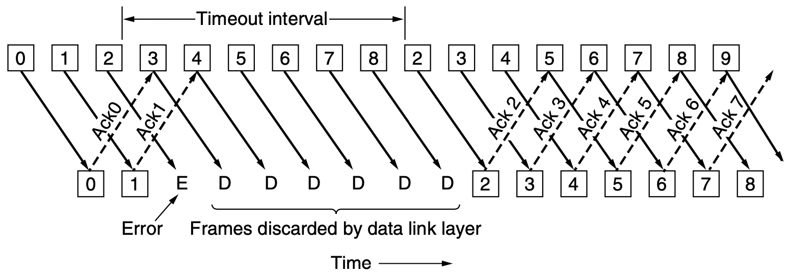
Notice the waste of bandwidth -
because the receiver only buffers a single frame,
all frames transmitted after a lost (or corrupted frame)
require later re-transmission -
we go back N frames and then restart transmitting.
CITS3002 Computer Networks, Lecture 3, Data Link Layer protocols, p26, 13th March 2024.
The Selective Repeat Protocol
The go-back-N protocol wastes bandwidth on retransmitted frames if the
error rate is high.
Alternatively,
in the selective repeat protocol,
the receiver can buffer all received frames (up to some limit)
and simply wait for the bad frame to be retransmitted.
- The sender's window size corresponds to the number of frames
transmitted by not yet received - it varies, grows and shrinks, over time.
- The receiver's window size corresponds to the number of frames
that the receiver is willing to receive - it too varies over time,
and is always ≥ 1.
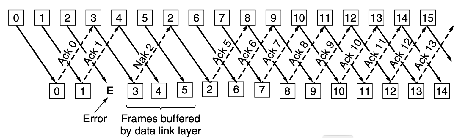
If the receiver receives a corrupted frame,
or one that is not at the lower edge of its receiving window,
a negative acknowledgment is sent,
indicating the highest correct frame that has been received to date.
CITS3002 Computer Networks, Lecture 3, Data Link Layer protocols, p27, 13th March 2024.
A Problem with Selective Repeat
Suppose that we use 3 bits to represent the sequence numbers (0..7),
even if we use a larger integer to store the sequence number
in an actual implementation.
Now, imagine that the following events happen, in order :
- Sender sends frames 0..6.
- All arrive correctly into the receiver's window as 0..6,
the receiver advances its window to 7,0,1,...,5
and acknowledges the frames.
- A "small disaster" occurs and no acknowledgements are received.
- The sender times out and resends frame 0.
- The receiver gets frame 0,
which is within its receiving window and says thanks.
The receiver acknowledges for frame 6 as it is still waiting on 7.
- Sender now sends new frames 7,0,1,...,5.
- Frame 7 is received and frames 7 and (the duplicated) 0 go off to
the network layer. Oops!
The Solution : make window sizes half the size of the
maximum sequence number.
CITS3002 Computer Networks, Lecture 3, Data Link Layer protocols, p28, 13th March 2024.
A Sample selective-repeat Protocol
Here we develop a sample selective-repeat protocol for the data
link layer.
We'll assume that the size of the sender's and receiver's windows
have been defined as integer constants with NRBUFS and MAXSEQ.
We omit the declaration of structures and variables,
but note that the sender will need a number of timers
(one per outstanding frame),
and the receiver needs record which frames have arrived
(but not yet to be sent to the layer above).
#include <cnet.h>
#include <stdlib.h>
#include <stdbool.h>

FRAME  *inframe;
FRAME  *outframe;

//  other declarations omitted....

EVENT_HANDLER(reboot_node)
{
    inframe   = calloc(NRBUFS, sizeof(FRAME));
    outframe  = calloc(NRBUFS, sizeof(FRAME));

    timers    = calloc(NRBUFS, sizeof(CnetTimerID));

    arrived   = calloc(NRBUFS, sizeof(bool));

    // we really should check if the allocations were successful!

    for(int b=0 ; b < NRBUFS ; b++) {
	arrived[b]    = false;
	timers[b]     = NULLTIMER;
    }

    CHECK(CNET_set_handler(EV_APPLICATIONREADY, appl_ready, 0));
    CHECK(CNET_set_handler(EV_PHYSICALREADY,    physical_ready, 0));
    CHECK(CNET_set_handler(EV_TIMER1,           DLL_timeouts, 0));

    CNET_enable_application(ALLNODES);
}
|
CITS3002 Computer Networks, Lecture 3, Data Link Layer protocols, p29, 13th March 2024.
A Sample selective-repeat Protocol, continued
When the layer above (here, the Application Layer) provides a message for
delivery,
we must now buffer that message for possible future retransmission.
Care is required to use the correct buffer!
As we also have a finite number of buffers in the sender,
we must choke or throttle
the Application Layer when our buffers are exhausted.
EVENT_HANDLER(appl_ready)
{
    CnetAddr dest;
    int      nf   = nextdatatosend % NRBUFS;

    outframe[nf].len   = MAX_MESSAGE_SIZE;

    CHECK(CNET_read_application(&dest, outframe[nf].msg, &(outframe[nf].len)));

    if(++nbuffered == NRBUFS) {         // out of buffer space!
	CNET_disable_application(dest);
    }
    transmit_frame(&outframe[nf], DL_DATA, FRAME_SIZE(outframe[nf]), nextdatatosend);
    inc(&nextdatatosend);
}
|
CITS3002 Computer Networks, Lecture 3, Data Link Layer protocols, p30, 13th March 2024.
A Sample selective-repeat Protocol, continued
We have most work to perform when a frame arrives at the Physical Layer -
either some DL_DATA or an DL_ACK.
As with earlier protocols,
we must first determine if the frame has been corrupted.
A more complex selective-repeat protocol may incorporate
DL_NACKs.
EVENT_HANDLER(physical_ready)
{
    FRAME     frame;
    int       link, checksum;
    size_t    len;

    len     = sizeof(FRAME);
    CHECK(CNET_read_physical(&link, &frame, &len));

    checksum          = frame.checksum;
    frame.checksum    = 0;

    if(CNET_ccitt((unsigned char *)&frame, len) != checksum) {
        return;       // bad checksum, simply ignore frame
    }
    if(frame.kind == DL_ACK) {
        if(between(ackexpected, frame.seqno, nextdatatosend)) {

            while(between(ackexpected, frame.seqno, nextdatatosend)) {
                --nbuffered;          // buffer now available

                CNET_stop_timer(timers[ackexpected % NRBUFS]);
                timers[ackexpected % NRBUFS] = NULLTIMER;
                inc(&ackexpected);
            }
            CNET_enable_application(ALLNODES);
        }
    }
|
CITS3002 Computer Networks, Lecture 3, Data Link Layer protocols, p31, 13th March 2024.
A Sample selective-repeat Protocol, continued
When a DL_DATA frame arrives,
we must ensure that it is within the receiver's range of expected frames.
For each frame in a sequence that have arrived successfully,
we send it to the layer above.
//  this is the continuation of event-handler  physical_ready

    else if(frame.kind == DL_DATA) {
	if(between(dataexpected, frame.seqno, toofar) &&
	    arrived[frame.seqno % NRBUFS] == false) {

	    arrived[frame.seqno % NRBUFS]    = true;
	    inframe[frame.seqno % NRBUFS]    = frame;   // copies frame

	    while(arrived[dataexpected % NRBUFS]) {
		len   = inframe[dataexpected % NRBUFS].len;
		CHECK(CNET_write_application( inframe[dataexpected % NRBUFS].msg, &len));

		arrived[dataexpected % NRBUFS] = false;
		inc(&dataexpected);
		inc(&toofar);
	    }
	}
	else {
	    ;    // frame is ignored/
        }
	transmit_frame(NULL,DL_ACK,0,(dataexpected+MAXSEQ)%(MAXSEQ+1) );
    }
}
|
We do not send an DL_ACK for each frame received;
instead we simply acknowledgment the 'highest' sequence number correctly
received to date.
This DL_ACK implies all 'lower' sequence numbers have been received
as well.
CITS3002 Computer Networks, Lecture 3, Data Link Layer protocols, p32, 13th March 2024.
|

 CITS3002