
|
CITS3002 Computer Networks |
 CITS3002
 |
 help3002
 |
 CITS3002 schedule
 |
|||||
Responsibilities of the Physical and Data Link LayersThe Physical and Data Link layers have strongly related responsibilities.
Physical Layer responsibilities:
Data Link Layer responsibilities:
CITS3002 Computer Networks, Lecture 2, The Physical Layer, Errors detection and correction, p1, 6th March 2024.
Metrics Of Network MeasurementThere are two components to performance - latency and bandwidth. We always want high bandwidth and low latency, but can't always get both together.
The latency of a message is the total time for the whole message to arrive:
    TLatency     = TPropagation + TTransmit + TQueue

    TPropagation = distance / speed-of-propagation-in-medium
    TTransmit    = message-size / bandwidth
    TQueue      = time-spent-in-local-and-remote-operating-system-and-switch-queues
On prefixesIn networking and data storage (devices), the prefix Mega means 106, at least when referring to throughput and bandwidth. We always use powers of 10 when referring to frequencies, measured in Hertz. When talking about the size of a message, buffer, file, or other computer-storage item, we use Mega to mean 220. Similar rules apply for the prefixes Kilo and Giga.See: Transmission time [Wikipedia], Binary prefix [Wikipedia], and Grace Hopper Explains a Nanosecond.
CITS3002 Computer Networks, Lecture 2, The Physical Layer, Errors detection and correction, p2, 6th March 2024.
The Physical Layer and Transmission Errors
Rates of transmission errors are described by their probability of occuring, or by their expected bit-error-rate (BER). Transmission errors usually occur in bursts and are caused by:
Over a particular time interval, a burst begins at the first bit that is corrupted (inverted), and ends at the last bit corrupted - the bits between are not necessarily all modified.
CITS3002 Computer Networks, Lecture 2, The Physical Layer, Errors detection and correction, p3, 6th March 2024.
Discussion question 1
Never underestimate the bandwidth of a station wagon full of tapes hurtling down the highway. Andrew Tanenbaum - "Computer Networks" 3rd ed., p83
... or 3.5Mbps over a piece of wet string (2017).
CITS3002 Computer Networks, Lecture 2, The Physical Layer, Errors detection and correction, p4, 6th March 2024.
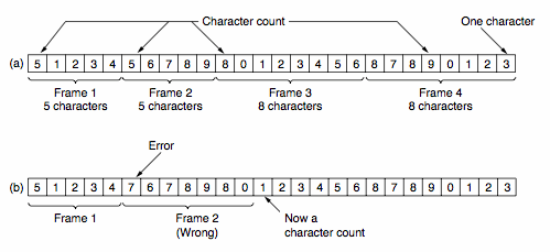
How Data is Placed in FramesSimple timing gaps between frames cannot be used as all hardware devices (as part of the Physical Layer) run at slightly different speeds; resulting in skewing if time is relied upon. A first attempt at a solution involves counting the size of a frame and placing this count in the data link header - blah!

This naive solution highlights problems with synchronization - assuming the receiver can detect a problem, how much of the arriving bit stream should be skipped to find the next frame?
CITS3002 Computer Networks, Lecture 2, The Physical Layer, Errors detection and correction, p5, 6th March 2024.
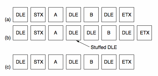
How Data is Placed in Frames, continuedTo overcome synchronization problems, special byte sequences are often used to prefix and suffix (envelope) the data. As these special bytes may themselves be required data we must "escape" their special meaning (particularly true for "binary" data such as floating point numbers, executables, JPGs and MP3s).
This process is termed byte stuffing,
using DLE=0208, STX=0028, ETX=0038.
Consider the following example, transmitting 3 bytes: [A, DLE, B]

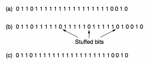
A lower-level approach, bit-stuffing, overcomes the reliance on using the ASCII codes. Each frame is now enveloped in pairs of "flag" patterns 01111110.

If this flag pattern appears in the data, the stuffed sequence 011111010 is transmitted.
CITS3002 Computer Networks, Lecture 2, The Physical Layer, Errors detection and correction, p6, 6th March 2024.
Phase Encoding of SignalsTo be able to detect collisions on LANs, we need to understand how digital signals are encoded on the physical medium. A digital signal is a sequence of discrete, discontinuous pulses, or signal elements. If all signal elements have the same (voltage) sign, they are termed unipolar. The modulation rate of a LAN is the number of signal elements (transitions) per second, or the baud rate. To correctly interpret a signal, the receiver must know the length (time) of each signal element and the expected voltage levels of the bits 0 and 1. The two simplest encoding schemes are the:

NRZ-I is an example of differential encoding in which the signal transition, rather than the signal level, indicates the value of each bit. See also: Sound of the dialup modem explained.
CITS3002 Computer Networks, Lecture 2, The Physical Layer, Errors detection and correction, p7, 6th March 2024.
Phase Encoding of Signals, continuedNRZ-L and NRZ-I are simple schemes, but unfortunately offer no possible synchronization. Another scheme, biphase encoding, ensures that there will be a transition in the middle of each bit. With Traditional Manchester encoding the mid-bit transition provides a clocking mechanism (as well as the data). With Differential Manchester the mid-bit transition provides the clocking and the initial transition provides the data.

Biphase encoding schemes have (at least) one transition per bit time, thus the maximum modulation rate, or baud rate, is twice that for NRZ-L and NRZ-I.
CITS3002 Computer Networks, Lecture 2, The Physical Layer, Errors detection and correction, p8, 6th March 2024.
Error Detection and CorrectionData may be modified so that errors can either be:
Correction is required where communication must be simplex (only possible in one direction), but correction is expensive. A good example of its need is between Earth and inter-planetary spacecraft. Error correction by the receiver is referred to as forward error correction, whereas re-transmission schemes are referred to as reverse error correction. Codewords are constructed consisting of both data and check bits.
The Hamming distance between two codewords consists of the number of
bit positions in which they differ.
e.g.	1 ⊕ 1  =  0 ⊕ 0  =  0
	1 ⊕ 0  =  0 ⊕ 1  =  1
	 10011101
	 10111110
     --------------
       ⊕ 00100011
Here, the Hamming distance is 3. The Hamming distance of a code is the minimum Hamming distance between any two words in that code.
CITS3002 Computer Networks, Lecture 2, The Physical Layer, Errors detection and correction, p9, 6th March 2024.
Error Detection and Correction, continuedTo detect: δ errors, a distance of δ + 1 is required. e.g. to detect 1 bit in error requires that there is no word with a distance of 1 from a valid word. To correct: δ errors, a distance of 2 δ + 1 is required so that even with δ errors, the damaged codeword is the closest to one valid codeword. Some examples :
Consider a simple encoding of ASCII characters,
where we use a parity code
[see Tanenbaum 5/e]
Consider a code whose only valid code words are :
0000000000 1111100000 0000011111 1111111111
CITS3002 Computer Networks, Lecture 2, The Physical Layer, Errors detection and correction, p10, 6th March 2024.
Hamming's Correction of Single-Bit Errors
Let's say that a single transmission consists of
m bits for the message,
and
r bits of seemingly redundant information.
The critical question is "how much additional information (the redundant bits) do we need to transmit so that the receiver can correct errors?" Each of the 2 m possible message words has n illegal code words which are a distance 1 from it. Therefore each message word requires n + 1 distinct bit patterns (1 legal one, and n illegal ones). In 1950, mathematician and Turing Award winner Richard Hamming developed a method which achieves the lower bound of:
m+r+1 <= 2 r.
Given a code word of 7 data bits and 4 check bits, we number the code word from 1 from the left hand side.
Each bit whose ordinal position is a power of 2 {1,2,4,8,...} is a check bit and forces the parity of some "collection" of bits including itself. Parity may be forced to be either even or odd.
CITS3002 Computer Networks, Lecture 2, The Physical Layer, Errors detection and correction, p11, 6th March 2024.
Hamming's Correction of Single Errors, continuedA data bit contributes to the parity of all bits in its decomposition into a sum of powers of 2. For example :
     3 = 2 + 1
     7 = 4 + 2 + 1
    11 = 8 + 2 + 1
Making a list of these :
    1 is contributed to by 3, 5, 7, 9, 11
    2                      3, 6, 7, 10, 11
    4                      5, 6, 7
    8                      9, 10, 11
We then put the data bits in their positions and calculate each check bit.
CITS3002 Computer Networks, Lecture 2, The Physical Layer, Errors detection and correction, p12, 6th March 2024.
Hamming's Correction of Single Errors, continuedFor example, ASCII character 'c' = 1100011, using even parity :
         1  2  3  4  5  6  7  8  9 10 11
        ---------------------------------
               1     1  0  0     0  1  1


check 1        X     X     X     X     X

check 2        X        X  X        X  X

check 3              X  X  X

check 4                          X  X  X
The resulting codeword is hence 11111000011. We then transmit this codeword across the network.
CITS3002 Computer Networks, Lecture 2, The Physical Layer, Errors detection and correction, p13, 6th March 2024.
Hamming's Correction of Single Errors, continuedWhen a codeword is received at the other end we must check (and possibly correct) it. To correct when it arrives: Initialize a counter, c, to 0. Examine each check bit in position k={1,2,4,8} to see if it has the correct parity. If not, add k to c. When all check bits have been examined, and counter c is 0, then codeword is correct. Otherwise, the incorrect bit is in position c. For example, if we transmit 11111000011 (from before), but we receive :
      1  2  3  4  5  6  7  8  9 10 11
     ---------------------------------
      1  1  1  1  1  0  0  0  0  1  0
c=0
k=1	parity for 3,5,7,9,11	wrong! so  c+=k  (=1)
k=2	parity for 3,6,7,10,11	wrong! so  c+=k  (=3)
k=4	parity for 5,6,7	correct
k=8	parity for 9,10,11	wrong! so  c+=k  (=11)
Hence bit 11 is in error!
CITS3002 Computer Networks, Lecture 2, The Physical Layer, Errors detection and correction, p14, 6th March 2024.
Cyclic Redundancy Codes (CRCs)The extra bits used to detect errors are called checksum bits. A checksum can be quite simple, for example "add-with-carry" all bytes in a message, or much more sophisticated as in the case of a cyclic redundancy code (or CRC). Polynomial Codes A polynomial is represented by a bit string with 1 for each power represented in the polynomial, and 0 otherwise. e.g. x4 + x3 + 1 is represented as 11001 Polynomial arithmetic is performed Modulo-2 or EXCLUSIVE-OR
e.g.	1 ⊕ 1  =  0 ⊕ 0  =  0
	1 ⊕ 0  =  0 ⊕ 1  =  1
Both the sender and receiver agree on a generator polynomial, G(x), with high and low order bits 1. The message, M, is also interpreted as a polynomial. The checksum (when calculated) is appended to the message so that (M + checksum), known as the transmission T(x), is divisible by G(x). On arrival we simply check that the received transmission is divisible by G(x). [See A Painless Guide to CRC Error Detection Algorithms]
For examples of other types of checksum algorithms, see the
Australian Securiities & Investment Commission and
CITS3002 Computer Networks, Lecture 2, The Physical Layer, Errors detection and correction, p15, 6th March 2024.
Polynomial Codes, continuedWhat types of errors can (and cannot) be detected with CRCs?
Let the error bits in Tarrived(x) be E(x).
Each bit in E(x) corresponds to a bit that has been inverted.
Then, due to the properties of the Modulo-2 arithmetic:
    (T(x) + E(x)) / G(x) = (T(x) / G(x)) + (E(x) / G(x))
                         =       0       + (E(x) / G(x))
We notice that if G(x) divides E(x) (because G(x) is a factor of E(x)), then errors can go by undetected. Some important results:
CITS3002 Computer Networks, Lecture 2, The Physical Layer, Errors detection and correction, p16, 6th March 2024.
Some Standard Polynomial Codes16 bit checksums catch -
CRCs are often performed in hardware, for example the DEC-VAX architecture (mid-1980s) had an assembly language instruction to perform CRC-16 (!). Today, all network interface cards (such as wired and wireless Ethernet) perform checksumming "on-board".
CITS3002 Computer Networks, Lecture 2, The Physical Layer, Errors detection and correction, p17, 6th March 2024.
|